The Jeffrey PCB – The History of the Board Development

Use this referral link to create an account at PCBWay, get a $5 discount, and help out my project.
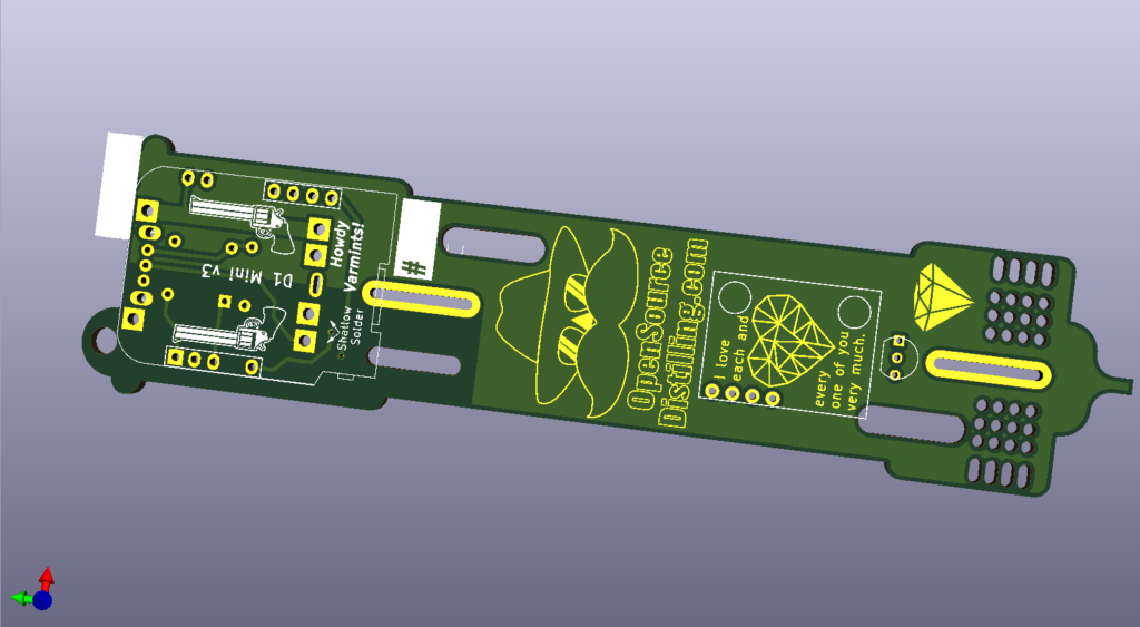
Most of the detail is in the video. Again, a big shout out to PCBWay for providing the prototypes free of charge. Below are some of the 3D renders.
Please leave comments here on my blog or on my youtube channel if you have suggestions.
The First Prototype


The Jeffrey 2.0
The Jeffrey 2.0 can be purchased here. Use this referral link to create an account, get a $5 discount, and help out my project.
PLEASE NOTE: Through-hole support for the battery holder has been discontinued after receiving feedback from the community. Only surface-mounted battery holders will be supported moving forward.


The Jeffrey 2.0 has Physically Arrived 🙂


The Jeffrey 2.1
The Jeffrey 2.1 can be purchased here. Use this referral link to create an account, get a $5 discount, and help out my project.
Minor improvements are completed on The Jeffrey 2.1. On the front I have changed the TP4056 footprint so that the two clusters of two-solder points are designed in such a way that they hold the pins in place for you while soldering. I found that sometimes it was difficult to solder these pins in place as they kept moving and didn’t fit in a breadboard. These newly placed through holes should make assembly a little easier.

On the back there are a few changes as well. The 230k resistor typo from the official iSpindel web page has been corrected to 220k. Previously there was a V formation and an additional elongated through-hole allowing two resistors to be added together to get to 230k but since that isn’t actually necessary it has been removed.

The Jeffrey 2.69

The Jeffrey 2.69 can be purchased here. Use this referral link to create an account, get a $5 discount, and help out my project.
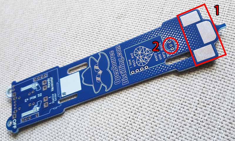
The changes on The Jeffery 2.69 are highlighted above in red.
- Oversized solder pads have been added. A large pad in the middle and two smaller pads on the sides. The middle pad should provide more than enough real estate to add solder to balance an offset calibrated iSpindel to 25 degrees in pure water.
- The temperature probe has been rotated 180 degrees so the rounded part of the probe lines up with the curved interior wall of the petling.


35 Comments
Nikos · February 7, 2020 at 10:53 AM
Where can i expect to buy The Jeffrey PCB ?
Joey Joe Joe Jr · February 7, 2020 at 5:23 PM
It will be available from PCBWay.com once I get my hands on it and do a quality check. The final prototypes were ordered a week and a half ago but the Chinese New Year Festival had caused delays. Hopefully, it will arrive soon. The PCB will be released with an assembly video.
Nikos · February 7, 2020 at 11:38 PM
OK great cant wait, let us know, this looks a lot better than the other alternative.
Joey Joe Joe Jr · February 19, 2020 at 9:57 AM
The final version of the PCB is now available.
https://www.pcbway.com/project/shareproject/iSpindel_The_Jeffrey_2_0___Open_Source_Distilling.html
Rod · February 8, 2020 at 6:45 AM
Will the giveaway planned for February 5th, be delayed until these new boards arrive from PCBWay.com?
Joey Joe Joe Jr · February 8, 2020 at 1:53 PM
I will release a video Monday announcing the winner and review the final version of The Jeffrey 2.0. Thanks for your patience.
Jeffery Schneider · February 10, 2020 at 11:44 AM
And when The Jeffrey 2.0 is available, do we buy from you? or from PCBWay?
Joey Joe Joe Jr · February 19, 2020 at 9:59 AM
Board is now available from PCBWay.
https://www.pcbway.com/project/shareproject/iSpindel_The_Jeffrey_2_0___Open_Source_Distilling.html
Gonzalo · February 10, 2020 at 11:59 AM
Great work redesigning the board. It looks really nice. Will you release the design files?
Joey Joe Joe Jr · February 19, 2020 at 10:00 AM
For now, the boards will only be available through PCBWay. Thanks for your comment!
https://www.pcbway.com/project/shareproject/iSpindel_The_Jeffrey_2_0___Open_Source_Distilling.html
Joey Joe Joe Jr · March 31, 2020 at 10:33 AM
Yo, the gerber files are now available on my GitHub at https://github.com/OpenSourceDistilling/The_Jeffrey_PCB.
Cheers!
Bruce · February 10, 2020 at 2:16 PM
Hi,
230K is not a Valid Resistor decade Value, The closest you will find will be the 230.7K or 232k
and that not easy, to find either , I will post some results after I dig around
Joey Joe Joe Jr · February 10, 2020 at 2:22 PM
Apparently, 230k is a typo in the original docs. I’m told that it should be 220k. Although it doesn’t matter too much as that resistor is used to measure the battery voltage and that reading can be calibrated via a factor inside the iSpindel configuration menu. Therefore, 220k or 230k or something close will work fine 🙂
Thomas · February 14, 2020 at 8:53 AM
Any chance to order these now via pcbway as you have received the final version?
Joey Joe Joe Jr · February 19, 2020 at 10:00 AM
Board is available now via PCBWay.
https://www.pcbway.com/project/shareproject/iSpindel_The_Jeffrey_2_0___Open_Source_Distilling.html
Marcelo · February 11, 2020 at 1:38 AM
Can’t wait for the The Jeffrey PCB 2.0. CHeers.
Joey Joe Joe Jr · February 19, 2020 at 10:01 AM
Available now! 🙂
https://www.pcbway.com/project/shareproject/iSpindel_The_Jeffrey_2_0___Open_Source_Distilling.html
jimdkc · February 11, 2020 at 11:11 PM
I’ve got parts on order… Can’t wait to order some boards!
Joey Joe Joe Jr · February 19, 2020 at 9:52 AM
They are available now 🙂
https://www.pcbway.com/project/shareproject/iSpindel_The_Jeffrey_2_0___Open_Source_Distilling.html
Rod · February 19, 2020 at 9:55 AM
I ordered 5 yesterday. Can you share some new videos of setting up the latest version through actual gravity readings?
Joey Joe Joe Jr · February 19, 2020 at 10:12 AM
Hey Rob, thanks for your order. I will be working on a video series showing assembly and all the calibrations and linking it to data services. I’m currently away on business this week then away on vacation next week. The assembly for this board will be pretty close to the CherryPhilips version (link below), except there will be the tabs to file down to fit it snuggly into the pelting. Install the battery in the lowest position as the one I built floated at 25.XX degrees in pure water without the need to add external weights which was a pleasant surprise. You can use a 220k resistor as 230k isn’t needed, either or will work though. New assembly video will follow when I return. Let me know if you need any assistance along the way.
Cheers,
Joey Joe Joe Jr.
http://opensourcedistilling.com/ispindel-assembly/
brouwkip · February 22, 2020 at 1:42 PM
I am about to order 5 of the ver2 boards but looking at your video it seems that the diode on the D1 was not removed.
do you or do you not have to remove the diode on the D1
Joey Joe Joe Jr · February 24, 2020 at 5:14 PM
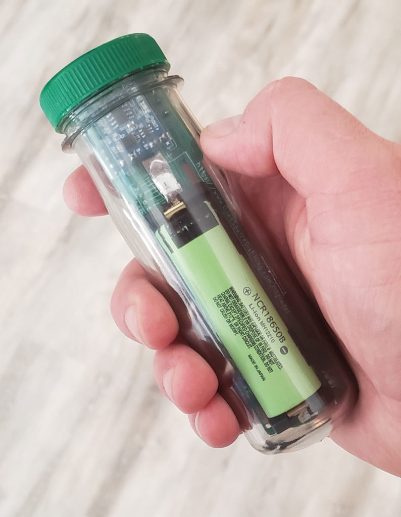
Yes, remove the diode. Removing it is a safety feature. Pelting dimensions are.
Parameters:
Color Clear, gently grey
Dimensions (external, MAX), mm ~135 x (d39, d43 MAX)
Dimensions (internal), mm
~123 x d33
Conversion: 1mm = 0.0393 inch, or 1 inch = 25.4mm
Eric · February 23, 2020 at 1:13 PM
I am about to order 5 spindel pcb’s and build them according to your instructions only on the video it does not seem you have removed the diode from the D1 is this still required? Also can you give me the dimensions of the petling, it is not always possible to order from amazon in The Netherlands.
Cheers,
Eric
Joey Joe Joe Jr · February 24, 2020 at 5:13 PM
Yes, remove the diode. Removing it is a safety feature. Pelting dimensions are.
Parameters:
Color Clear, gently grey
Dimensions (external, MAX), mm ~135 x (d39, d43 MAX)
Dimensions (internal), mm
~123 x d33
Conversion: 1mm = 0.0393 inch, or 1 inch = 25.4mm
Eric · February 26, 2020 at 4:16 AM
Thanx
Joey Joe Joe Jr · March 3, 2020 at 12:05 PM
No prob. Those pelting specs are from the ebay page I link to. They should deliver worldwide.
Sergey · March 3, 2020 at 11:45 AM
Hello! Cool design, good work. I ordered 10 boards. Just do not understand how the battery holder is attached. Will the holders with pins fit?
Joey Joe Joe Jr · March 3, 2020 at 12:03 PM
No pins, they are surface mounted like these ones.
An assembly vid will be coming out soon. Just got back from 2 weeks of being out of town. You just tin the contacts on the battery holder and tin the pads on the PCB. Put in position then apply heat, they will fuse together. This config makes it easy to move the battery holder later if need be. Also, these battery holders tend to be cheaper.
Nikos · March 3, 2020 at 12:01 PM
When can we expect your construction video for the board ?
Joey Joe Joe Jr · March 3, 2020 at 12:08 PM
It’s in the editing room now. Hopefully in the next week. Time is a little tight right now as I just got back into town after being away for 2 weeks.
Eric · March 3, 2020 at 12:27 PM
Beautiful, I’ve ordered the boards and the rest of the supplies and they will not arrive within a month
jimdkc · March 4, 2020 at 5:19 PM
I have my boards and all of my parts except for the battery holders. Looking forward to the adventure to come!
Vytautas · April 24, 2020 at 11:57 PM
I noted that 2.1 is in the works… Is this far away or should I just order the 2.0 board?
Joey Joe Joe Jr · April 25, 2020 at 1:02 AM
The changes are small. I correct the typo for the 230k resistor (from the official iSpindel webpage schematic) to the correct value of 220k. I also tighten up a few of the TP4056 solder points, the two 2-blocks, so that the PCB holds them in place as you solder as I found them a little tricky during assembly, and I want to make construction easier for everyone. I changed a few small esthetic things and removed an unnecessary through hole. It will essentially be the same board with minor revisions after getting feedback from the community. PCBWay is manufacturing prototypes right now and once I quality control them I will release them to the public. I’m not sure how long that will be since the whole pandemic thing is going on. Truth be told the new version won’t warrant a new assembly video. Since the changes are small and unnoticeable in the final product I would say don’t wait, order when you are ready to.